
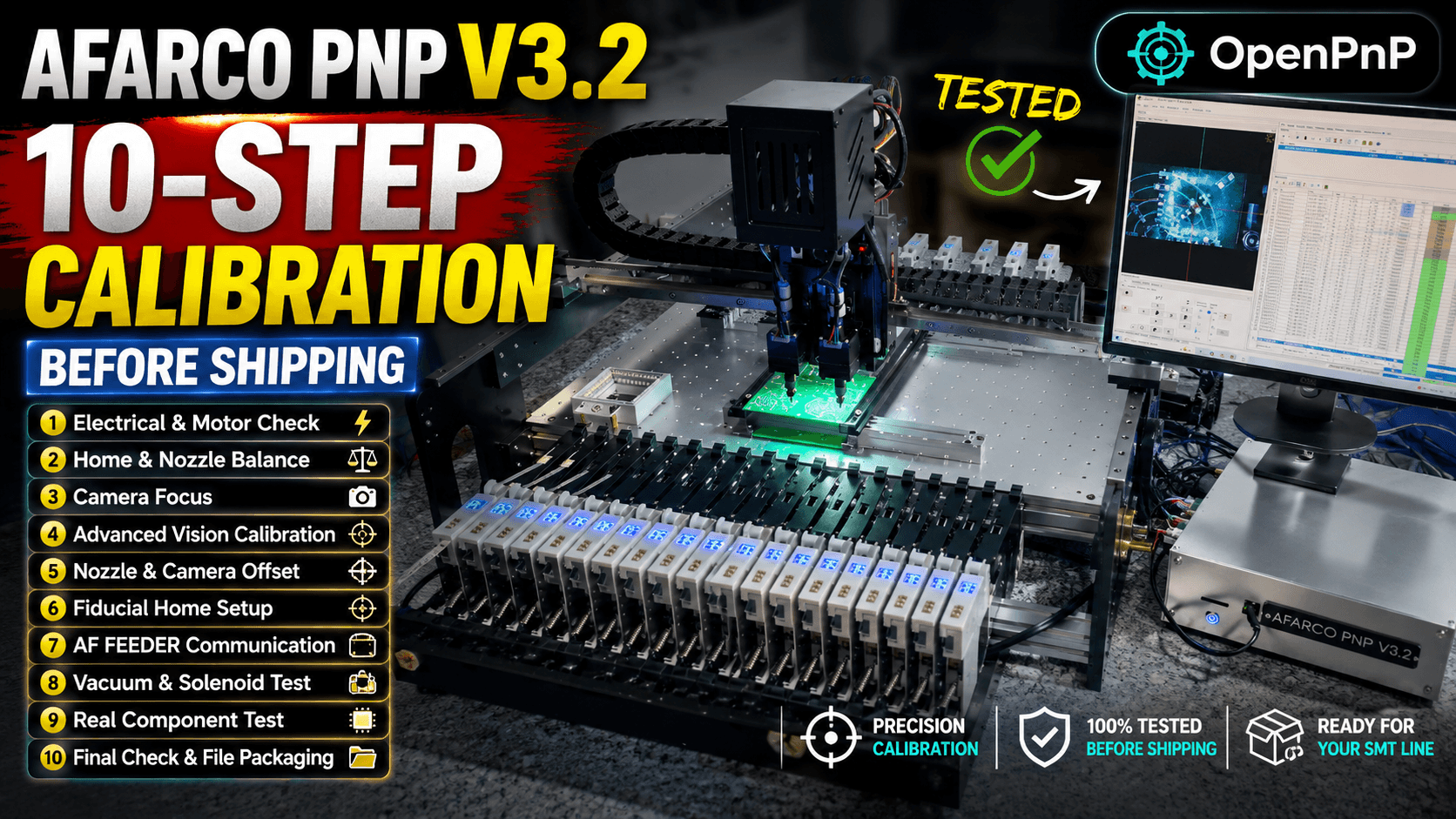
How We Calibrate an OpenPnP Pick and Place Machine: 10-Step AFARCO PNP V3.2 Pre-Shipping Test
Building a precision desktop pick and place machine is only part of the challenge.
Before a machine is ready for real SMT assembly, its motion system, nozzles, cameras, feeders, vacuum system, and OpenPnP configuration all need to work together accurately.
At AFARCO, every PNP V3.2 goes through a structured inspection and calibration process before shipping.
In this article, we will walk through the 10-step calibration and testing workflow we use to prepare an AFARCO PNP V3.2 for delivery, while also explaining how these procedures relate to OpenPnP machine setup and calibration.
Watch the complete AFARCO PNP V3.2 calibration process on YouTube:
Why Calibration Matters on a Pick and Place Machine
A pick and place machine is a system of interconnected mechanical, electrical, pneumatic, and vision components.
A small error in one part of the system can eventually appear as a placement error on the PCB.
For example:
- Incorrect motor configuration can affect positioning.
- Incorrect axis scaling can create X/Y dimensional errors.
- Incorrect nozzle offsets can move components away from their intended locations.
- Camera focus and scale affect computer vision measurements.
- Camera-to-nozzle offsets affect where the machine believes a component should be picked or placed.
- Poor fiducial calibration can introduce board alignment errors.
- Incorrect feeder coordinates can cause pick failures.
- Insufficient vacuum can result in dropped or incorrectly picked components.
This is why calibration should not be treated as a single adjustment.
It is better understood as a chain:
Motion → Homing → Nozzles → Cameras → Vision → Fiducials → Feeders → Vacuum → Real Components → Final Validation
OpenPnP's current setup documentation also emphasizes that machine configuration consists of multiple interdependent stages, including driver setup, axes, cameras, steps per millimeter, nozzles, actuators, vacuum, feeders, vision, and homing-related functions.
For a production machine, the final objective is not simply to make every individual subsystem work.
The objective is to make the complete system work together.
The AFARCO PNP V3.2 10-Step Calibration Process
Our pre-shipping process consists of ten main stages.
- Electrical and motor configuration inspection
- Machine homing and N1/N2 nozzle alignment
- Camera focus and vision setup
- Advanced camera calibration
- Nozzle-to-camera offset calibration
- Fiducial Home setup
- AF FEEDER communication test
- Vacuum pump and solenoid valve test
- Real component placement test
- Final inspection and configuration file packaging
Let's look at each stage in more detail.
1. Electrical Connections, Voltage, Microstepping and Motor Current
Before performing precision calibration, the machine's electrical system must be checked.
This includes:
- Power connections
- Motor connections
- Limit and home switches
- Controller connections
- Camera connections
- Feeder communication
- Vacuum and actuator wiring
- Supply voltages
- Stepper motor configuration
- Microstepping configuration
- Motor operating current
This stage is important because mechanical calibration cannot compensate for an incorrectly configured motion system.
Microstepping and Motion Resolution
Stepper motor systems commonly use microstepping to divide a motor's full step into smaller increments.
In an OpenPnP machine, the controller and OpenPnP configuration must agree about the relationship between controller steps and physical movement.
OpenPnP describes the axis resolution as the smallest coordinate change that the software should consider, and for a typical stepper system this corresponds to the displacement of a microstep or a practical multiple of it.
The important point is that microstepping is not simply a software setting.
The complete motion chain must agree:
Motor → Driver → Microstepping → Mechanical transmission → Controller → OpenPnP
If any of these parameters are incorrect, the machine can appear to move correctly while its actual position is wrong.
Motor Current
Motor current also needs to be appropriate for the motor and driver.
Too little current can cause:
- Missed steps
- Reduced holding torque
- Unstable motion
Too much current can cause:
- Excessive motor temperature
- Driver temperature
- Unnecessary mechanical stress
For this reason, we verify the electrical configuration before continuing to precision calibration.
2. Machine Home Position and N1/N2 Nozzle Alignment
After the electrical system is verified, we establish a repeatable machine reference.
The first step is homing.
OpenPnP uses the homing operation to establish a known machine position. After homing, OpenPnP can use the configured home coordinates as the reference for subsequent movements.
For a machine with multiple nozzles, such as the AFARCO PNP V3.2, the relationship between the nozzles and the machine coordinate system is especially important.
Our machine uses two nozzles:
- N1
- N2
Both need to be aligned and characterized correctly.
Why Two-Nozzle Alignment Matters
Imagine that N1 is correctly aligned but N2 has a small X/Y offset.
The machine may successfully pick a component using N2, but the component could be placed at a slightly different location than expected.
This becomes especially important when working with:
- 0402 components
- 0603 components
- Fine-pitch ICs
- Small QFN packages
- High-density PCBs
OpenPnP treats nozzles as objects attached to a machine head and uses head offsets to describe their relationship with the other tools on the head.
Therefore, nozzle offsets must be accurately established before relying on the vision system for precision placement.
3. Camera Focus and Basic Vision Calibration
The camera is effectively the machine's measuring instrument.
If the camera cannot produce a sharp and stable image, computer vision cannot reliably determine where a component, fiducial, nozzle tip, or other feature is located.
The AFARCO PNP V3.2 uses machine vision as an important part of its OpenPnP workflow.
During calibration, we verify:
- Camera focus
- Lens position
- Camera orientation
- Image quality
- Lighting
- Working distance
- Camera-to-machine relationship
- Units-per-pixel calibration
Why Camera Focus Matters
A camera that is slightly out of focus may still look acceptable to a human operator.
Computer vision can be much less forgiving.
Edges become less defined, feature detection becomes less stable, and small changes in lighting can produce different results.
The camera should therefore be mechanically secure and focused at the actual working plane.
OpenPnP's camera setup documentation also recommends securing the camera lens after focusing so that mechanical movement does not unintentionally change the focus.
4. Advanced Camera Calibration
Basic camera setup is not always enough for a precision pick and place machine.
OpenPnP provides advanced camera calibration functionality to characterize the camera more accurately.
This can account for effects such as:
- Camera scale
- Camera position
- Camera orientation
- Lens distortion
- View-axis errors
- Different calibration Z heights
The objective is to make the relationship between the machine's physical coordinate system and the camera image as accurate as possible.
Why Advanced Calibration Is Important
A camera does not necessarily behave like an ideal mathematical projection.
For example, an object near the center of the image may have a slightly different apparent scale or position than the same object near the edge.
This becomes more important when the camera is used over a large field of view.
OpenPnP's Advanced Camera Calibration procedure can move the nozzle/camera system through multiple positions and calibration points to characterize these effects.
This is particularly useful for machines where the camera is used over a relatively large workspace.
5. Nozzle-to-Camera Offset Calibration
This is one of the most important calibration steps.
OpenPnP needs to know exactly where the nozzle is relative to the camera.
Consider this simple situation:
The camera sees the center of a component at:
X = 100.00 mm
Y = 50.00 mm
But the nozzle is physically offset from the camera.
If OpenPnP does not know that offset, the nozzle will not arrive at the same physical location.
The result can be:
- Incorrect pick position
- Incorrect placement position
- Fiducial alignment errors
- Vision-related placement errors
Head Offsets
OpenPnP defines camera and nozzle positions relative to the machine head.
The top/down-looking camera is commonly used as a reference, while the nozzle offsets describe the physical distance between the camera and each nozzle.
For a dual-nozzle machine, N1 and N2 must each have accurate offsets.
This is why we perform individual calibration for both nozzles.
6. Nozzle Tip Calibration and Runout Compensation
Nozzle calibration goes beyond simply measuring the distance between the nozzle and camera.
A nozzle tip can have mechanical runout.
In other words, when the nozzle rotates, its tip may not remain perfectly centered.
Even a small eccentricity can affect placement accuracy.
OpenPnP provides a dedicated Nozzle Tip Calibration system that uses the bottom camera and computer vision to measure:
- Nozzle tip runout
- Precise nozzle-tip position
- Camera relationship
- Calibration background information
The calibration can measure the nozzle tip at multiple rotation angles and calculate the runout.
OpenPnP can then compensate for this runout during operation.
This is particularly valuable for machines with rotating nozzles and precision SMT placement requirements.
7. Fiducial Home Setup
A fiducial is a visual reference feature used by OpenPnP to determine a precise physical location.
Fiducials are commonly used to determine the position and rotation of a PCB.
They can also be used for visual homing.
What Is a Fiducial Home?
Mechanical homing establishes the machine's coordinate reference using hardware such as limit or home switches.
A visual homing system can then use a known fiducial to refine the machine's X/Y position.
The process is essentially:
Mechanical Home → Camera Finds Fiducial → Coordinate Correction
This can help compensate for small repeatability errors in the mechanical homing process.
OpenPnP documentation describes visual homing as a process where the machine performs its normal homing operation and then uses a defined homing fiducial to establish the final coordinate reference.
Fiducial Quality Matters
The fiducial used for calibration should be:
- High contrast
- Round
- Flat
- Sharp
- Clearly detectable
- At a known Z height
OpenPnP's vision documentation specifically recommends avoiding fiducials with significant 3D depth because viewing them from different angles can introduce apparent position errors.
The Z position is particularly important because camera scale depends on the distance between the camera and the surface being observed.
8. AF FEEDER Communication and Operation Test
A pick and place machine is only as useful as its ability to reliably obtain components.
This makes feeder testing another important part of the production process.
OpenPnP supports several feeder architectures, including strip feeders, tray feeders, tube feeders, auto feeders, and slot-based automated feeders.
The AFARCO PNP V3.2 uses the AF FEEDER ecosystem to provide automated component feeding.
Before shipping, we verify the feeder communication and operation.
The test includes checking:
- Communication with the feeder system
- Feeder addressing
- Feed commands
- Mechanical feeding
- Pick position
- Feeder response
- Component presentation
Feeder Position Is Critical
OpenPnP defines a feeder pick location as the position where the nozzle goes to pick the component.
The Z position is also important.
The nozzle should reach the correct height so that it can reliably pick the component without applying unnecessary mechanical force.
A feeder that communicates correctly but presents the component at the wrong physical location can still cause pick failures.
Therefore, feeder testing needs to include both:
Communication + Mechanical Operation
9. Vacuum Pump and Solenoid Valve Testing
Picking a component requires more than simply moving the nozzle to the correct location.
The vacuum system must generate enough suction to securely hold the component.
The pneumatic system typically includes:
- Vacuum pump
- Tubing
- Solenoid valve
- Nozzle
- Vacuum actuator/control
- Optional vacuum sensing
During production testing, we verify that the vacuum system responds correctly.
We check:
- Pump operation
- Valve switching
- Vacuum generation
- Air leakage
- Nozzle response
- Vacuum release
- Component pickup
Vacuum Sensing
OpenPnP can also use vacuum sensing to determine whether a pick or place operation was successful.
The OpenPnP vacuum sensing system can read a pressure sensor and compare the measured vacuum against configured Part-On and Part-Off thresholds.
This creates an additional layer of process control.
Instead of assuming that a component was picked because the nozzle moved correctly, the machine can potentially verify that the component is actually present.
For production-oriented SMT automation, this type of feedback can be extremely valuable.
10. Real Component Placement Test
After the individual systems have been checked, we perform the most important test:
Use the machine to actually pick and place components.
This is where the entire calibration chain is tested simultaneously.
The machine must coordinate:
OpenPnP → Motion Controller → X/Y/Z/C Axes → Camera → Nozzle → Feeder → Vacuum → PCB
A real component test can reveal problems that are not obvious during individual subsystem testing.
For example:
- The machine may home correctly but have a small nozzle offset.
- The camera may be focused but incorrectly scaled.
- The feeder may communicate but present components slightly off-center.
- The vacuum system may work but fail to hold a specific component.
- Vision may detect the component but produce inconsistent rotation.
This is why real component testing is an essential final validation step.
What We Look For During the Real Placement Test
Depending on the component, we check:
Pick Accuracy
Does the nozzle consistently pick the component near its intended center?
Component Holding
Does the vacuum securely hold the component during movement?
Vision Detection
Can OpenPnP consistently identify the component?
Rotation
Does the component maintain the correct orientation?
Placement Position
Does the component land at the intended X/Y position?
Placement Rotation
Is the component orientation correct after placement?
Repeatability
Can the machine perform the operation repeatedly without accumulating errors?
The objective is not simply to achieve one successful placement.
The objective is repeatable performance.
Why Calibration Order Matters
One of the most important lessons from machine calibration is that the steps should not be performed randomly.
Many calibration procedures depend on earlier calibration results.
For example:
Incorrect machine coordinates
can lead to:
↓
Incorrect nozzle offsets
which can lead to:
↓
Incorrect camera relationship
which can lead to:
↓
Incorrect vision calibration
which can lead to:
↓
Incorrect placement
This is why OpenPnP's setup documentation provides a logical sequence for machine configuration and recommends using the current Issues & Solutions system for supported calibration procedures.
The modern OpenPnP workflow is increasingly centered around Issues & Solutions rather than manually editing machine configuration files.
For a new machine, this is an important distinction.
A Practical Calibration Sequence for a Desktop Pick and Place Machine
A practical workflow can therefore look like this:
Stage 1 — Electrical
Verify power, wiring, controller, motors, switches, cameras, feeders and actuators.
Stage 2 — Motion
Configure axes, microstepping, resolution, direction, homing and movement.
Stage 3 — Mechanical Reference
Establish machine home and verify repeatable coordinates.
Stage 4 — Nozzles
Configure N1 and N2 and establish their head offsets.
Stage 5 — Camera
Focus the camera and verify image quality, orientation and scale.
Stage 6 — Vision Calibration
Perform the appropriate OpenPnP camera and vision calibration.
Stage 7 — Nozzle Calibration
Calibrate nozzle-to-camera offsets and, where applicable, nozzle-tip runout.
Stage 8 — Fiducials
Configure the home fiducial and verify visual homing.
Stage 9 — Feeder and Vacuum
Test component feeding, vacuum generation and pneumatic control.
Stage 10 — Real SMT Test
Pick and place real components and verify repeatability.
This sequence minimizes the chance of calibrating one system using incorrect information from another system.
Common Calibration Problems
1. The nozzle does not appear centered in the camera
Possible causes include:
- Incorrect nozzle head offset
- Incorrect camera location
- Incorrect camera rotation
- Mechanical misalignment
- Nozzle-tip runout
OpenPnP provides tools and calibration procedures specifically for establishing the relationship between nozzles and cameras.
2. Placement accuracy changes after nozzle rotation
This can indicate nozzle-tip runout.
Nozzle Tip Calibration and runout compensation can be used to characterize and compensate for this effect.
3. Fiducial detection works in the center but becomes unreliable elsewhere
Possible causes include:
- Lens distortion
- Incorrect camera calibration
- Poor lighting
- Incorrect units-per-pixel calibration
- Fiducial Z-height differences
Advanced camera calibration can help characterize camera behavior across the field of view.
4. The feeder communicates but the nozzle misses the component
Communication is only one part of feeder operation.
Check:
- Feeder position
- Pick location
- Feeder Z height
- Component presentation
- Camera calibration
- Nozzle offset
5. The machine picks components but drops them during movement
Check:
- Vacuum level
- Tubing
- Solenoid valve
- Nozzle tip
- Component size
- Pick height
- Vacuum sensing thresholds
Why We Test Every Machine Before Shipping
For a DIY machine, it can be tempting to think that calibration is something the customer should perform after receiving the machine.
However, a properly calibrated machine can significantly reduce the amount of initial setup required by the customer.
At AFARCO, our goal is therefore to deliver more than a mechanically assembled machine.
We want the customer to receive a system that has already been:
- Electrically tested
- Mechanically checked
- Homed
- Vision calibrated
- Nozzle calibrated
- Feeder tested
- Vacuum tested
- Tested with real components
- Configured for OpenPnP
- Verified before shipment
The final configuration files are then prepared together with the machine so that the customer has a known starting point.
Calibration Is Not the Same as Machine Accuracy
It is also important to understand that calibration cannot compensate for every mechanical problem.
A machine must first have a sound mechanical structure.
Calibration can help compensate for:
- Known offsets
- Camera geometry
- Nozzle runout
- Coordinate relationships
- Certain repeatable system errors
But it cannot magically eliminate:
- Loose mechanical components
- Excessive backlash
- Poor belt tension
- Flexible structures
- Unstable mounting
- Incorrect Z heights
- Poor-quality electrical connections
This is why precision machine design and calibration need to work together.
A good calibration system starts with a mechanically stable machine.
OpenPnP as the Software Foundation
One of the reasons we use OpenPnP for the AFARCO PNP platform is its flexible architecture.
OpenPnP provides a software environment for integrating:
- Motion control
- Cameras
- Nozzles
- Feeders
- Fiducials
- Vision
- Vacuum sensing
- PCB placement
- Machine configuration
It is particularly interesting for DIY and small-scale SMT automation because users can build and adapt machines around an open software ecosystem rather than being locked into a proprietary machine architecture.
For AFARCO, this makes OpenPnP an important part of the overall PNP ecosystem.
From Calibration to Production
The ultimate purpose of calibration is not to produce impressive numbers on a configuration screen.
It is to make the machine perform a real SMT assembly task reliably.
A calibrated machine should be able to:
- Home consistently.
- Locate the board.
- Locate fiducials.
- Move accurately to feeders.
- Pick components.
- Verify or maintain component pickup.
- Use vision to determine component position.
- Move to the correct PCB location.
- Place the component.
- Repeat the process.
That is the real test.
Calibration is successful when the complete machine becomes predictable.
AFARCO PNP V3.2: From Factory Calibration to SMT Assembly
The AFARCO PNP V3.2 is designed around the OpenPnP ecosystem and combines precision motion, machine vision, multiple nozzles, automated feeding and vacuum control into a desktop SMT assembly platform.
Our 10-step pre-shipping calibration process is designed to reduce the gap between:
Machine Assembly
and
Real SMT Production
The machine is not considered ready simply because it powers on.
It needs to move correctly.
It needs to see correctly.
It needs to pick correctly.
It needs to place correctly.
And the complete system needs to work together.
Final Thoughts
A desktop pick and place machine is a precision system, and calibration is one of the most important steps between building the machine and using it for real PCB assembly.
The OpenPnP ecosystem provides powerful tools for machine setup, camera calibration, nozzle calibration, fiducial detection, feeder configuration and placement verification.
Our approach at AFARCO is to combine these OpenPnP capabilities with a structured factory testing process.
The result is a repeatable workflow:
Build → Inspect → Calibrate → Test → Verify → Package → Ship
For anyone building a DIY pick and place machine, working with OpenPnP, or developing a desktop SMT assembly system, understanding this calibration chain can make a significant difference in machine reliability and placement performance.
And for us at AFARCO, the final calibration is not the end of the machine-building process.
It is the point where the machine is ready to begin doing real work.
Related Topics
- OpenPnP Pick and Place Machine
- DIY Pick and Place Machine
- Desktop SMT Assembly
- OpenPnP Camera Calibration
- OpenPnP Nozzle Calibration
- OpenPnP Fiducial Calibration
- SMT Feeder Setup
- Pick and Place Machine Vision
- AFARCO PNP V3.2
- AF FEEDER
- DIY SMT Automation
shareShare this article