
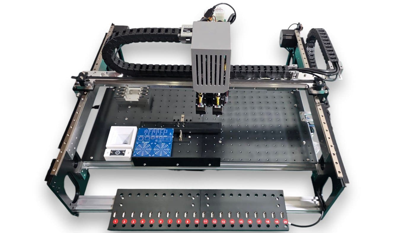
The AFARCO PnP V3.4 is the latest version of our desktop SMT pick-and-place machine, and it updates the earlier AFARCO PnP V3.2. This guide walks you through assembling a V3.4 kit step by step, with a photo for every action.
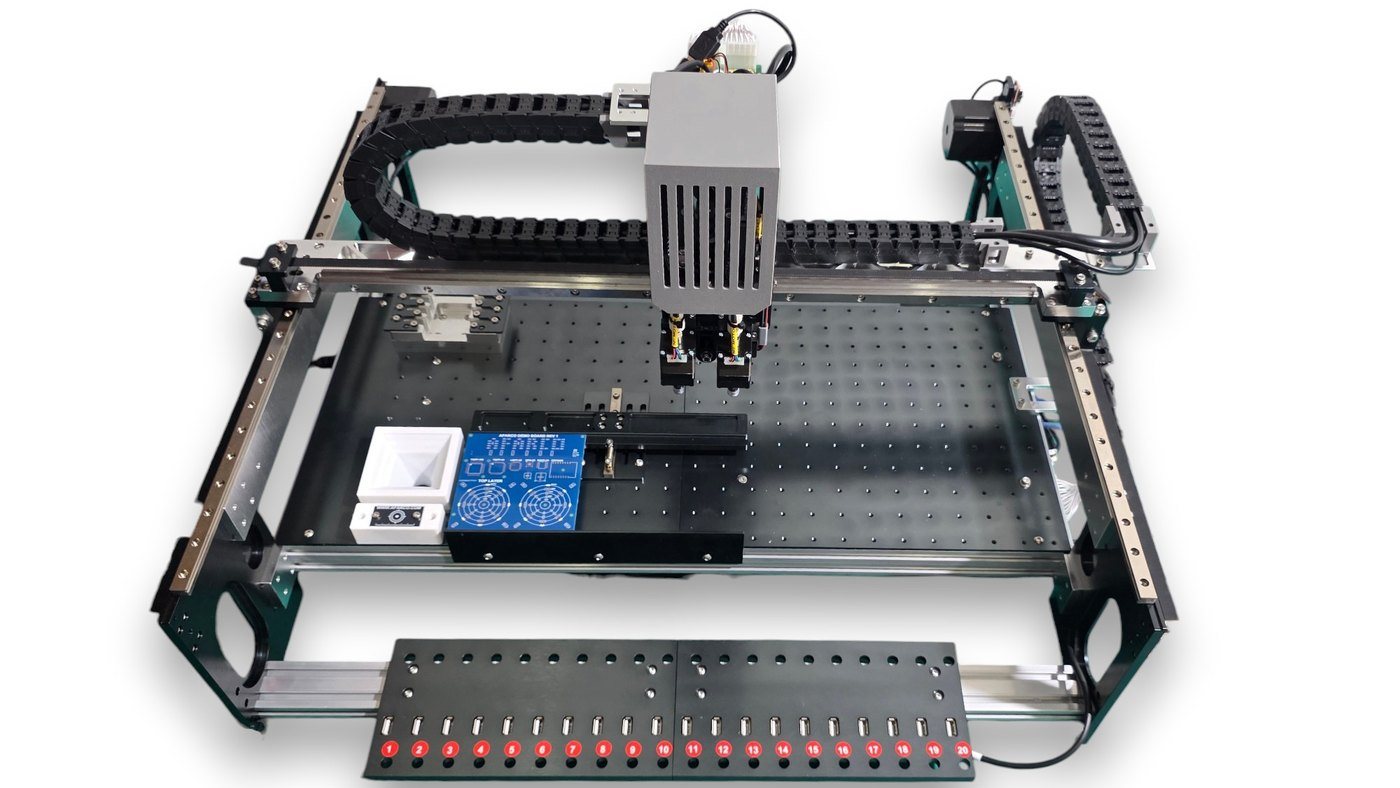
What is the AFARCO PnP V3.4?
The AFARCO PnP V3.4 is a desktop SMT pick-and-place machine that combines industrial-grade rigidity with the flexibility of the open-source OpenPnP ecosystem.
- High precision and repeatability. A precision-machined CNC aluminum frame and linear guideways deliver accurate placement of fine-pitch and small-footprint components.
- Easy to assemble and maintain. The placement head, pneumatic system, and external control box are cleanly laid out for straightforward assembly, troubleshooting, and upgrades.
- Flexible, cost-effective operation. The machine is fully compatible with OpenPnP. It supports a wide range of feeders and quick changeovers between PCB designs.
Upgrading from the AFARCO PnP V3.2
If you already know the AFARCO PnP V3.2, the core platform will look familiar. Both versions share:
- A dual-head design with independent N1 and N2 rotary axes on the Z-axis assembly.
- A 40-position AF Feeder system: 20 positions at the front and 20 at the rear.
- A 6-position nozzle station for automatic nozzle changes.
- Top and bottom cameras for machine vision.
- A Mean Well LRS-350-24 power supply (24 V, 350 W) with a selectable 110 V or 220 V AC input.
- Compatibility with OpenPnP on Windows and Ubuntu.
What's new in the AFARCO PnP V3.4
The V3.4 keeps the proven V3.2 platform and refines it. Machine size, build quality, and structure are unchanged.
- Redesigned PCB clamp with 20 mm of clearance. The space between the PCB surface and the tabletop is now 20 mm, up from 10 mm on the V3.2. This is an ideal height for flipping a PCB over to populate the second side without the board snagging on components already placed.
- Lighter Z-axis, same rigidity. The aluminum parts keep their original thickness (6 mm, 8 mm, and so on). Material is removed only in non-load-bearing areas, where the parts are machined thinner, and a few areas are made more compact to save space. We prioritize stiffness over weight savings. The Z-axis travel is unchanged.
- Same footprint, better layout. The overall machine dimensions are unchanged. We optimized the internal layout without changing the product's structure or build quality.
- Cleaner wiring that is easier to assemble. The main improvement is the electrical wiring. Cables are routed more neatly and are secured at fixed points on the machine frame, which makes assembly easier and gives a more polished look.
- Minor cosmetic refinements. There are small changes in color and spatial arrangement compared with the V3.2.
This guide covers the V3.4 assembly sequence. For the full V3.2 specifications, see the AFARCO PnP V3.2 product page.
Before you begin
Estimated assembly time: about 20 minutes.
Warning: Electrical hazard. Keep the AC power cord disconnected until all other cable connections are complete (Step 10). Set the input voltage selector (Step 1) before the machine is ever connected to mains power.
Caution: Moving parts. When the machine is powered, keep fingers, hair, and loose clothing away from the axes and cable chains.
Note: Do not force parts that do not fit. The axes are located by machined features and pins, and they seat without adjustment.
Workspace and environment
- Use a flat table, at least 700 × 750 mm (27.6 × 29.5 in), to hold the machine.
- Place the machine on a flat, stable surface, away from direct sunlight.
- Use a room with steady lighting that does not change constantly. Stable light keeps the machine-vision camera image consistent.
What you need to provide
- A complete AFARCO PnP V3.4 kit.
- Hex (Allen) keys to fit the supplied screws.
- A computer running Windows or Ubuntu, with at least 3 USB ports. Connect the Top Camera and Bottom Camera directly to two separate ports for stable bandwidth. The USB MAIN and USB RS485 connections can share the third port through a USB hub.
What's in the box
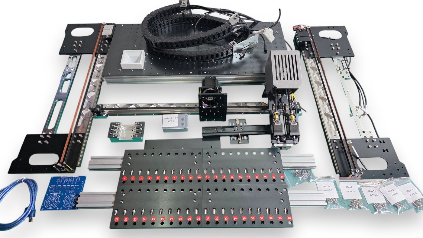
- Y1 axis assembly (left) and Y2 axis assembly (right)
- X axis assembly
- Z-axis assembly, including the N1 and N2 rotary axes
- 6-position nozzle station
- Cable chain set
- IEC power cord
- AF Feeder base, front (1–20)
- AF Feeder base, rear (21–40)
- PCB clamp set
- AFARCO demo PCB
- Tabletop assembly, including the Bottom Camera, control box, and AC-DC power supply
- USB Type-A to Type-B cables
- Screw kit
Fasteners at a glance
| Step | Fastener | Qty | Used for |
|---|---|---|---|
| 2 | M6×12 mm | 8 | Y1 and Y2 axes to tabletop (4 per axis) |
| 3 | M6×20 mm | 8 | AF Feeder base rails |
| 4 | M4×14 mm | 8 | X axis to Y1 and Y2 carriages |
| 6 | M4×8 mm | 3 | Z-axis assembly to X carriage |
| 7 | M4×10 mm | 8 | Cable chains |
| 8 | M4×8 mm + nut | 3 + 3 | PCB clamp, fixed part |
| 9 | M4×8 mm | 4 | Nozzle station |
Assembly overview
- Set the AC input voltage
- Attach the Y1 and Y2 axis assemblies
- Install the AF Feeder bases
- Install the X axis
- Check the X and Y axes
- Install the Z-axis assembly
- Install the cable chains
- Install the PCB clamp
- Install the nozzle station
- Connect the cables and power
Part 1: Prepare
Set the power supply for your local mains voltage.
Step 1: Set the AC Input Voltage
The AC-DC power supply (Mean Well LRS-350-24) is mounted under the tabletop. Set its input voltage selector to match your mains supply before you do anything else.
Warning: Set the voltage selector before the machine is connected to mains power. An incorrect setting can damage the power supply. The label on the power supply also says to check the input voltage setting before power-on.
1. Turn the tabletop upside down. The AC-DC power supply is on the underside.
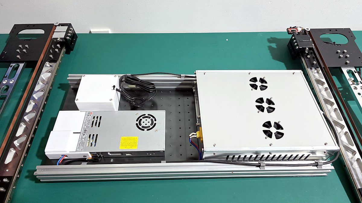
2. Find the voltage selector switch on the power supply.
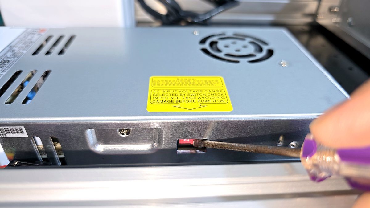
3. Set the switch to match your mains voltage:
- 115 V position – for 110–120 VAC mains.
- 230 V position – for 220–240 VAC mains.
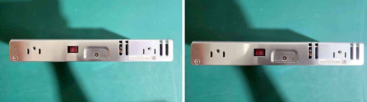
4. Turn the tabletop right side up.
Checkpoint: The voltage selector matches your mains supply.
Part 2: Frame
Attach the Y axes to the tabletop and install the AF Feeder bases.
Step 2: Attach the Y1 and Y2 Axis Assemblies
Parts and fasteners for this step
- Y1 axis assembly (“Y1” marked on the motor) and Y2 axis assembly (“Y2” marked on the motor)
- Tabletop assembly
- 8 × M6×12 mm screws (4 per axis)
1. Lay out the parts: Y1 axis on the left, Y2 axis on the right, and the tabletop between them.
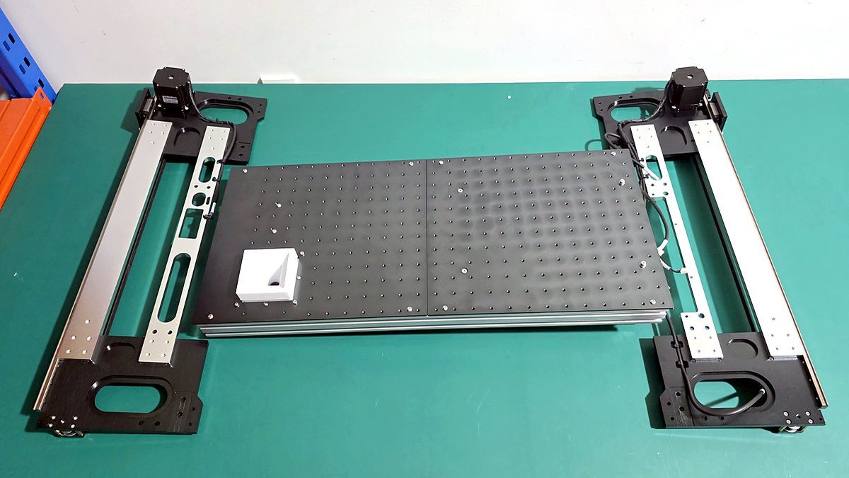
2. Install the Y2 axis first. Position it against the tabletop.
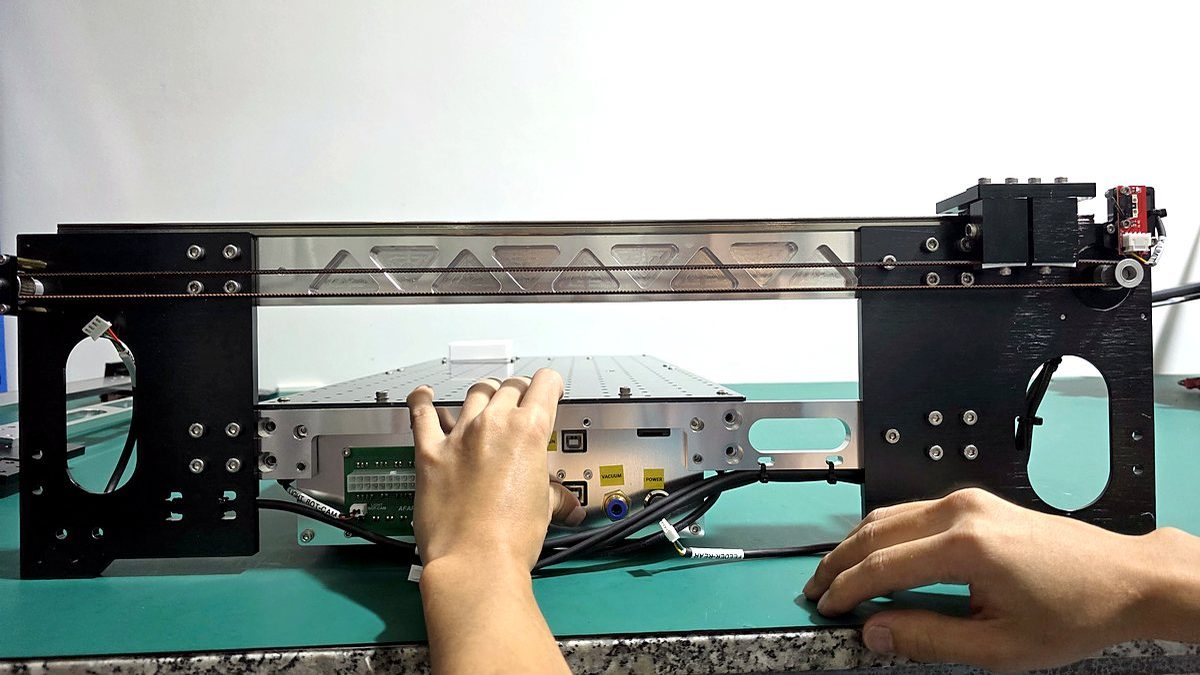
3. Secure the Y2 axis with four M6×12 mm screws.
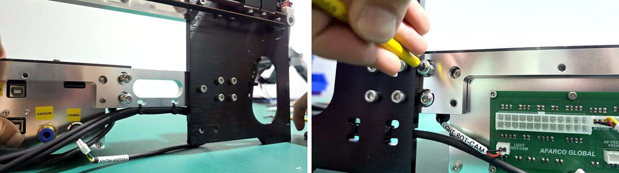
4. Check the result.
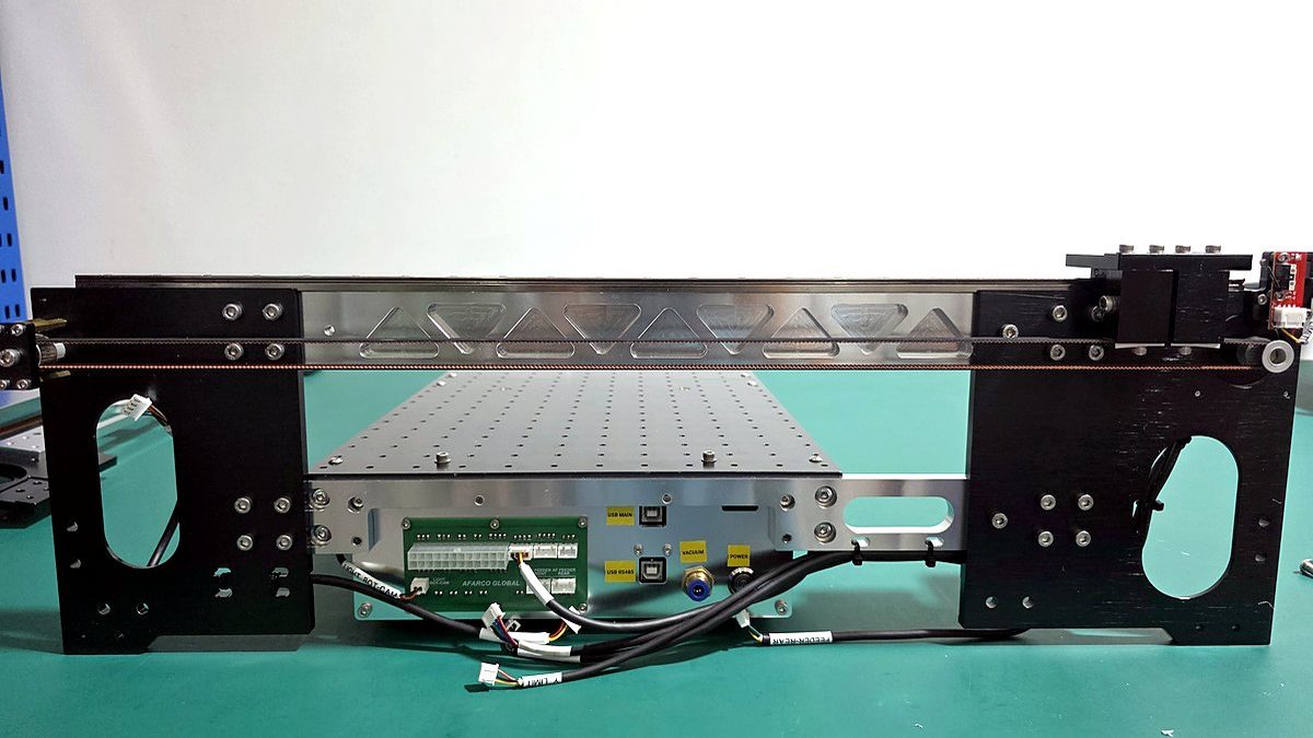
5. Repeat for the Y1 axis: position it, then secure it with four M6×12 mm screws.

6. Check the result. Both Y axes are now attached to the tabletop.

Step 3: Install the AF Feeder Bases
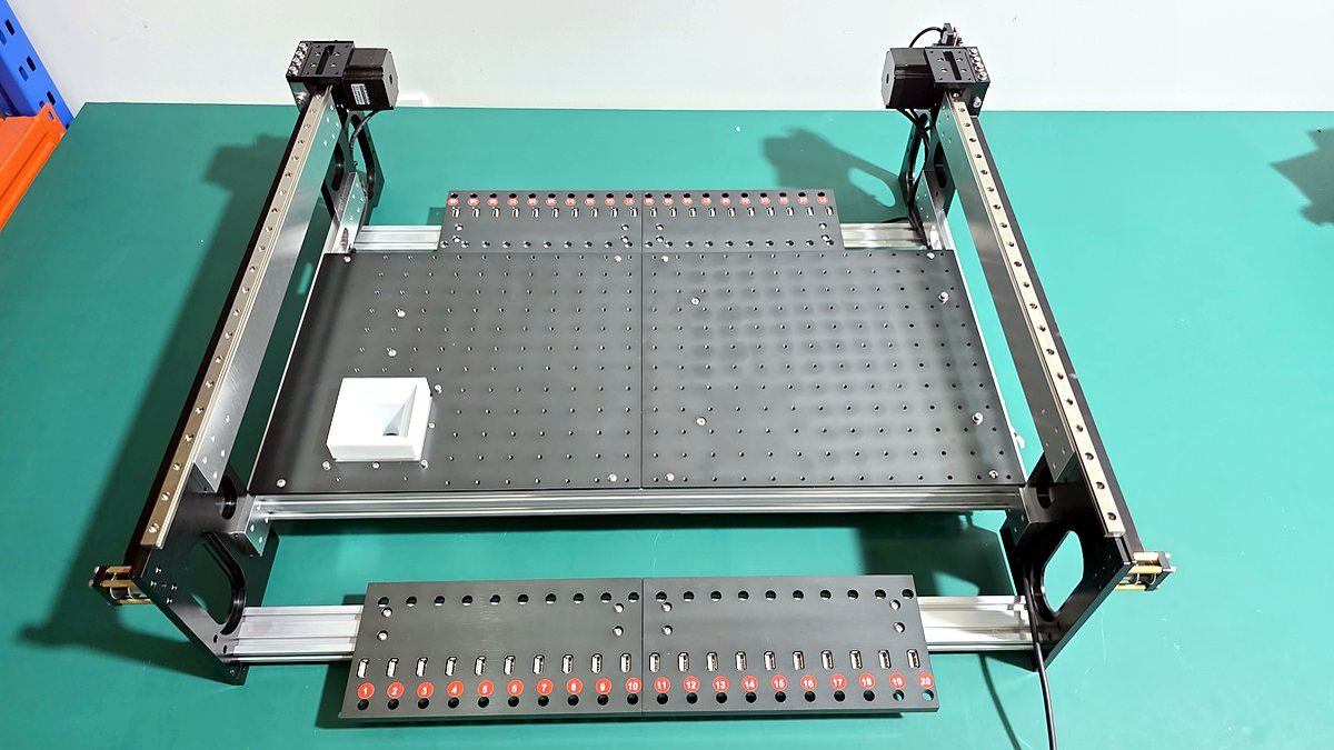
The machine has two AF Feeder bases. The front base is numbered 1–20. The rear base is numbered 21–40. Each base is mounted on an aluminum extrusion rail.
Parts and fasteners for this step
- AF Feeder base, front (1–20)
- AF Feeder base, rear (21–40)
- 8 × M6×20 mm screws (in total)
1. Identify the front base (1–20) and the rear base (21–40).
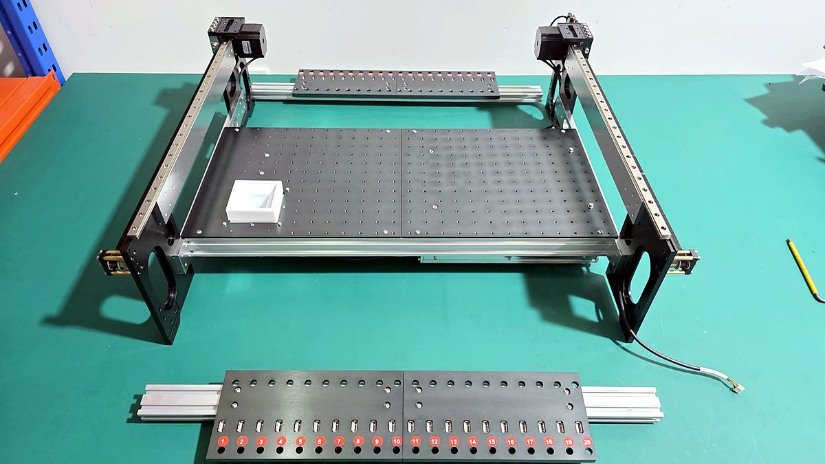
2. Slide each base’s aluminum rail into the machined guide channels on the Y1 and Y2 plates.
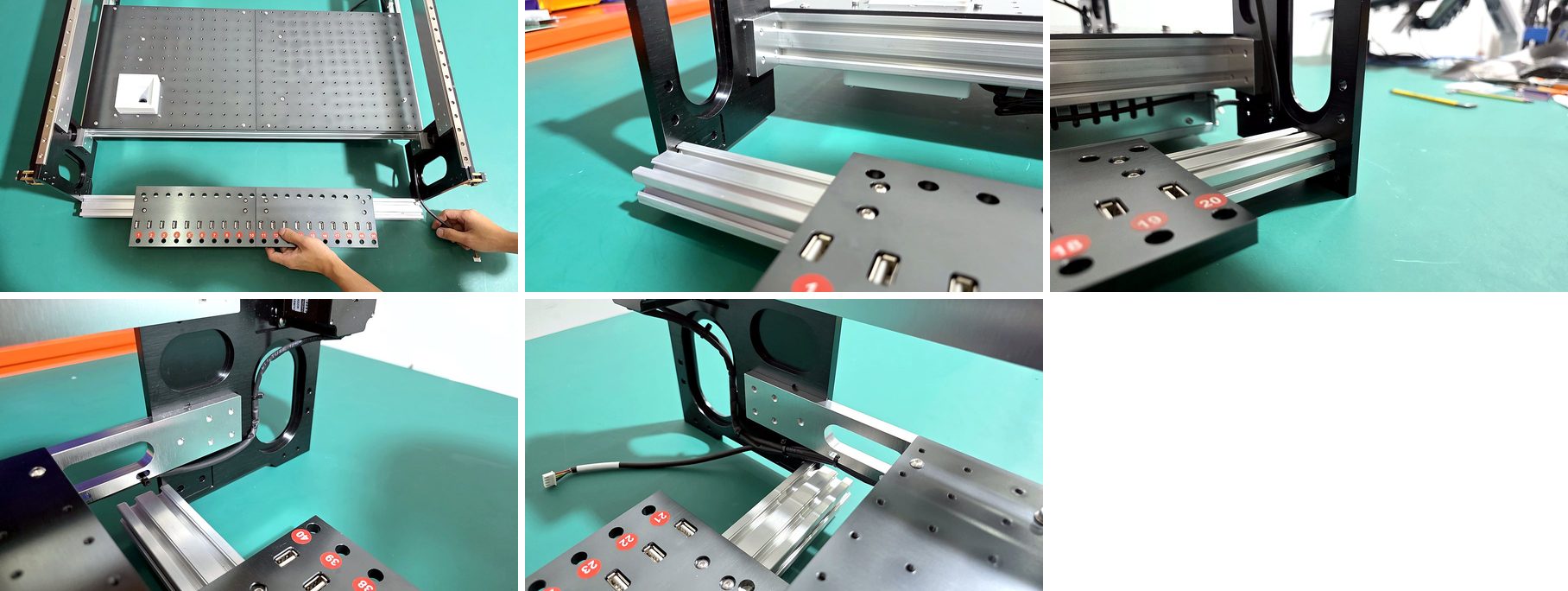
3. Fasten the rails with eight M6×20 mm screws in total.
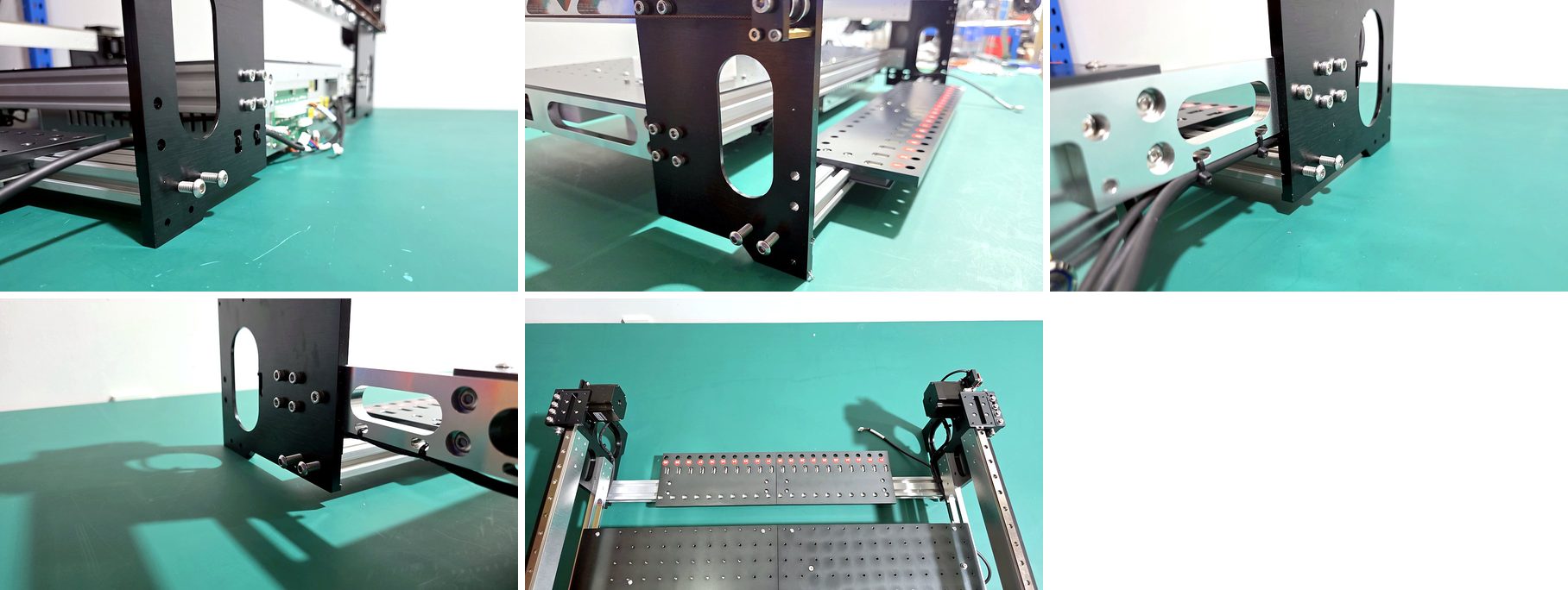
4. Check the result.
5. Tilt the frame 90° so that you can reach the underside.
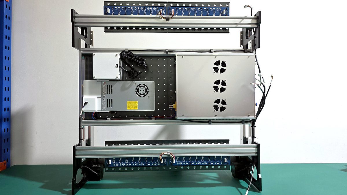
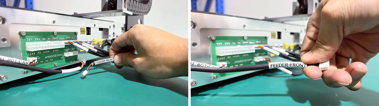
6. Connect the FEEDER-FRONT signal cable to the front AF Feeder base.
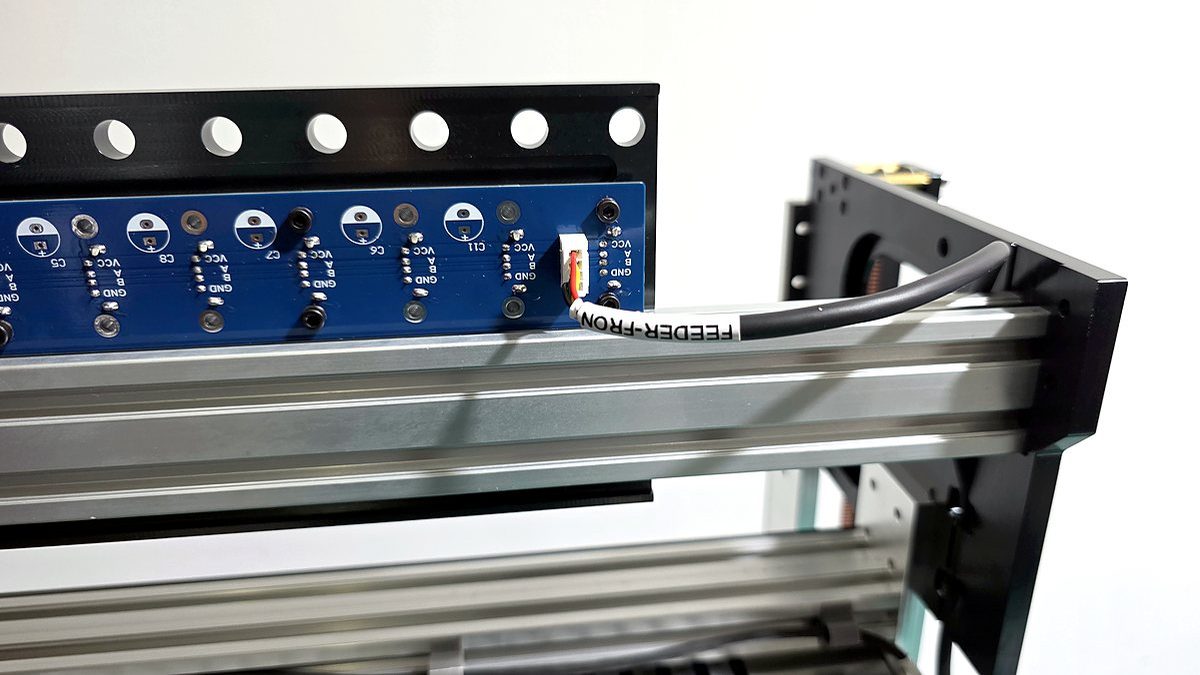
7. Connect the FEEDER-REAR signal cable to the rear AF Feeder base.
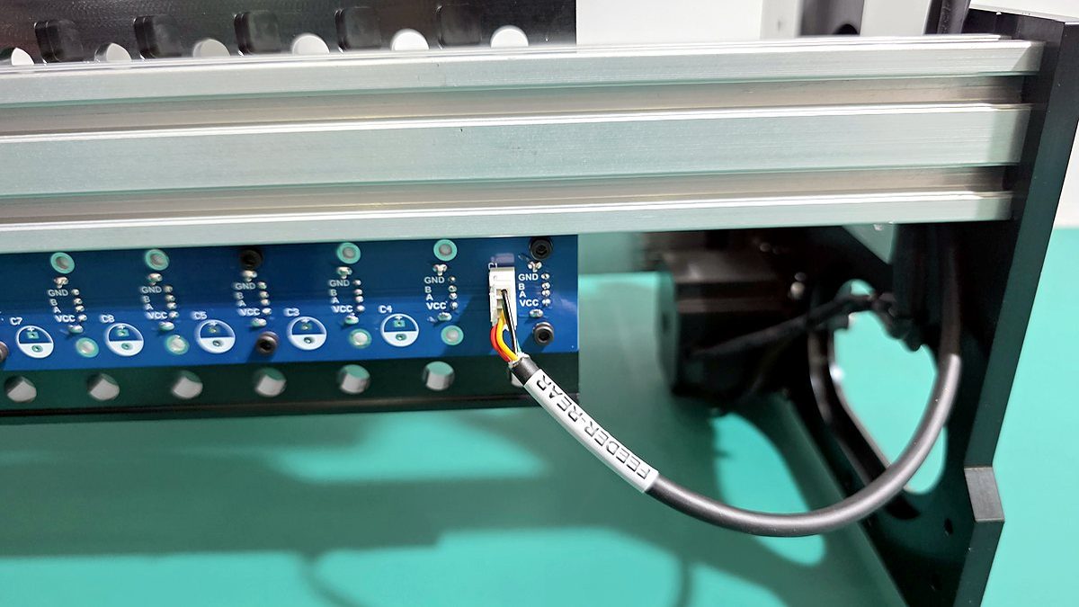
8. Connect the Y1 motor signal cable.
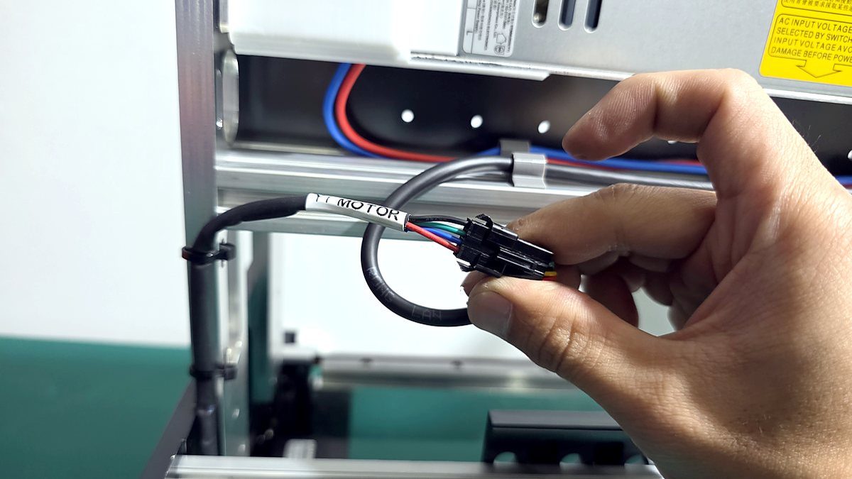
9. Free the Bottom Camera USB cable and route it out of the frame. You will connect it to the computer later.
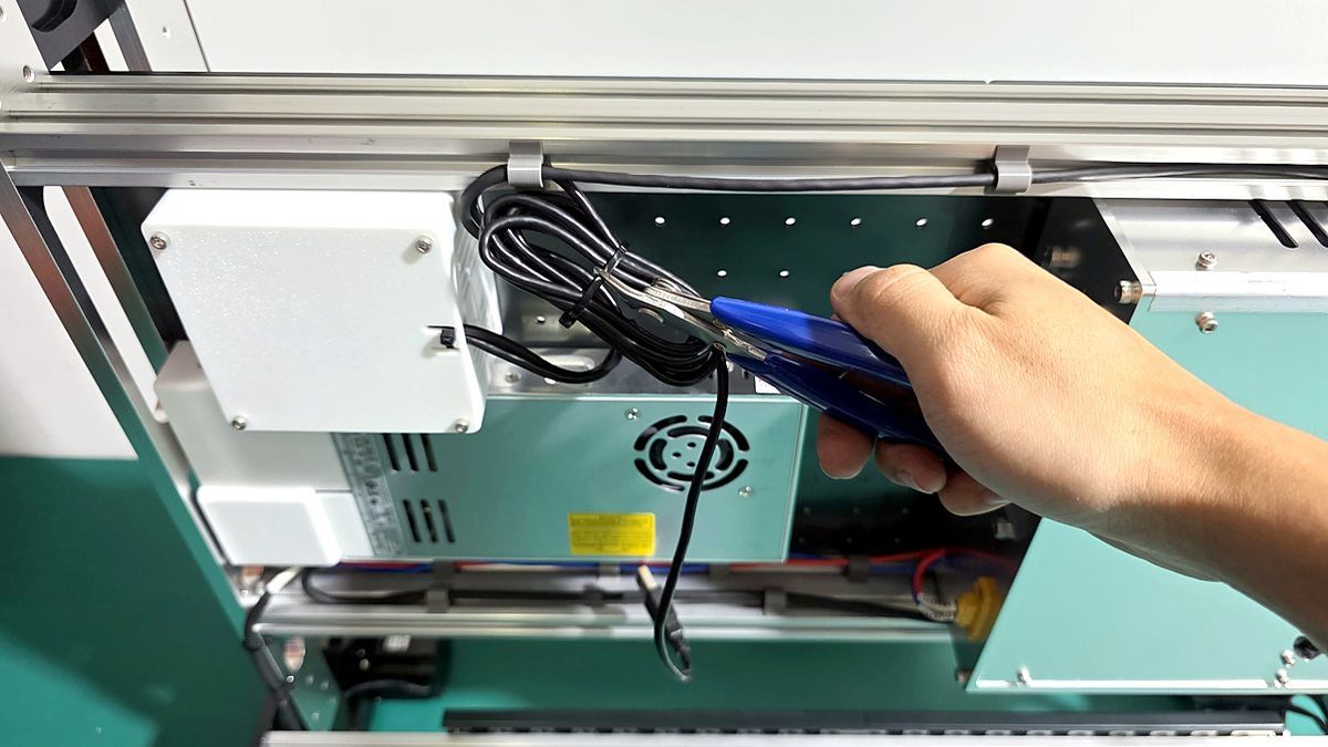
Checkpoint: The Y1 and Y2 axes are bolted to the tabletop. Both AF Feeder bases are installed with their signal cables connected. The Bottom Camera USB cable is routed out of the frame.
Part 3: Motion System
Install the X axis, Z axis, and cable chains.
Step 4: Install the X Axis
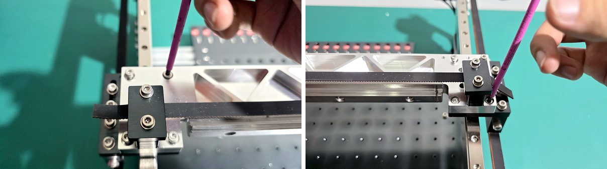
The X axis and the Y axes locate against each other through machined male/female features. Place the X axis in position – no alignment adjustment is needed.
Parts and fasteners for this step
- X axis assembly
- 8 × M4×14 mm screws
1. Find the machined locating features on the Y1 and Y2 carriages.
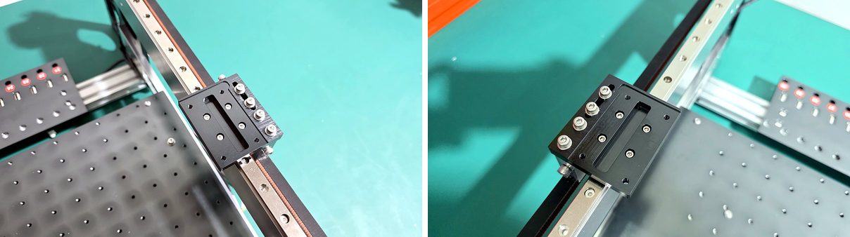
2. Seat the X axis squarely into the right-angle corner of the locating features on both Y1 and Y2.

3. Secure the X axis with eight M4×14 mm screws.
4. Check the result.
Step 5: Check the X and Y Axes
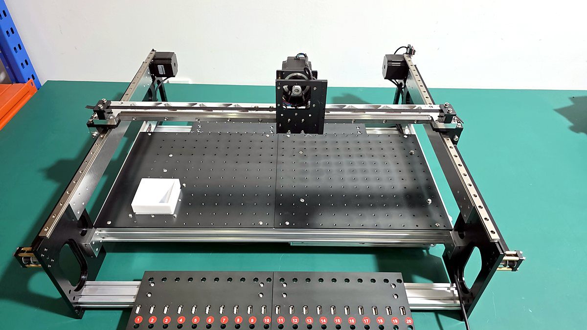
Move the axes by hand before you continue. Do not power the machine for this check.
1. Hold the X axis and slide it along the full Y travel. The motion should be smooth, with no binding. At the end of the Y travel, the Y limit switch should be actuated.
2. Slide the X carriage left and right along the full X travel. The motion should be smooth. At the end of the X travel, the X limit switch should be actuated.
Step 6: Install the Z-Axis Assembly
The Z-axis assembly includes the N1 and N2 rotary axes. It locates on the X carriage through a machined male/female interface and a locating pin.
Parts and fasteners for this step
- Z-axis assembly (with N1 and N2 rotary axes)
- 3 × M4×8 mm screws
1. Fit the Z-axis assembly onto the locating pin on the X carriage.
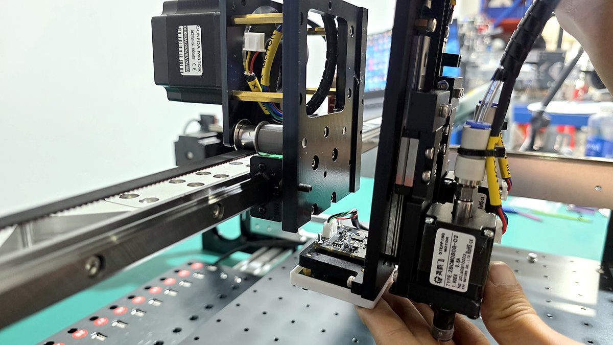
2. Secure it with three M4×8 mm screws.

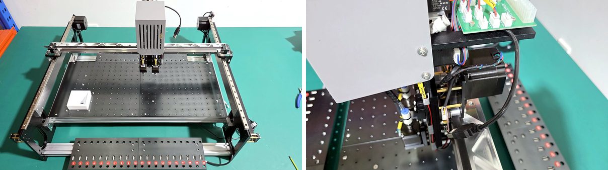
3. Check the result.
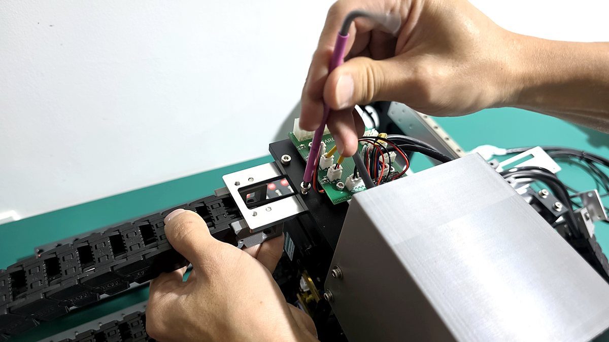
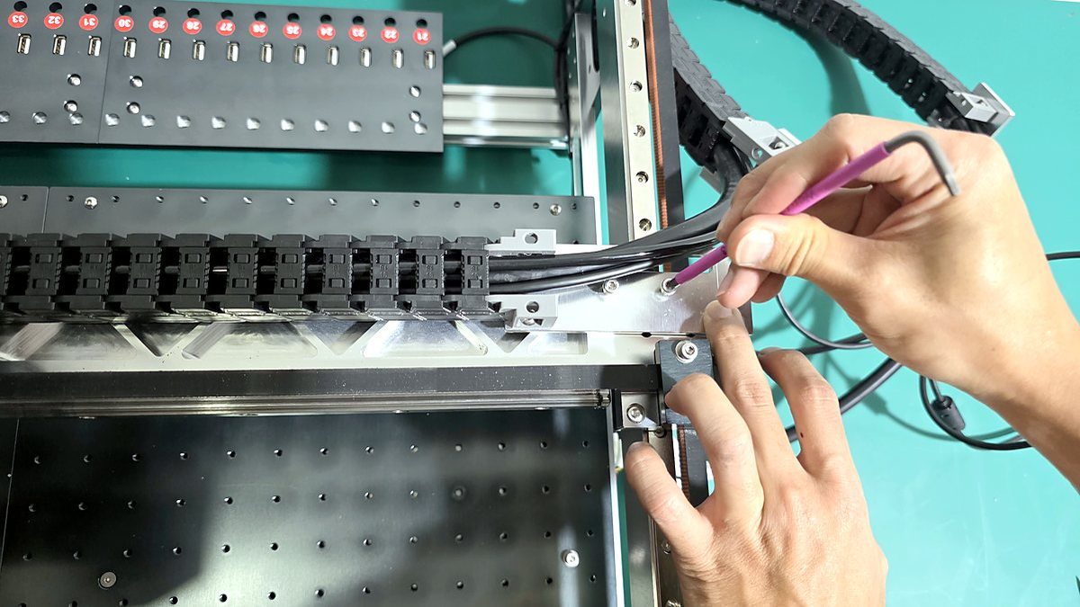
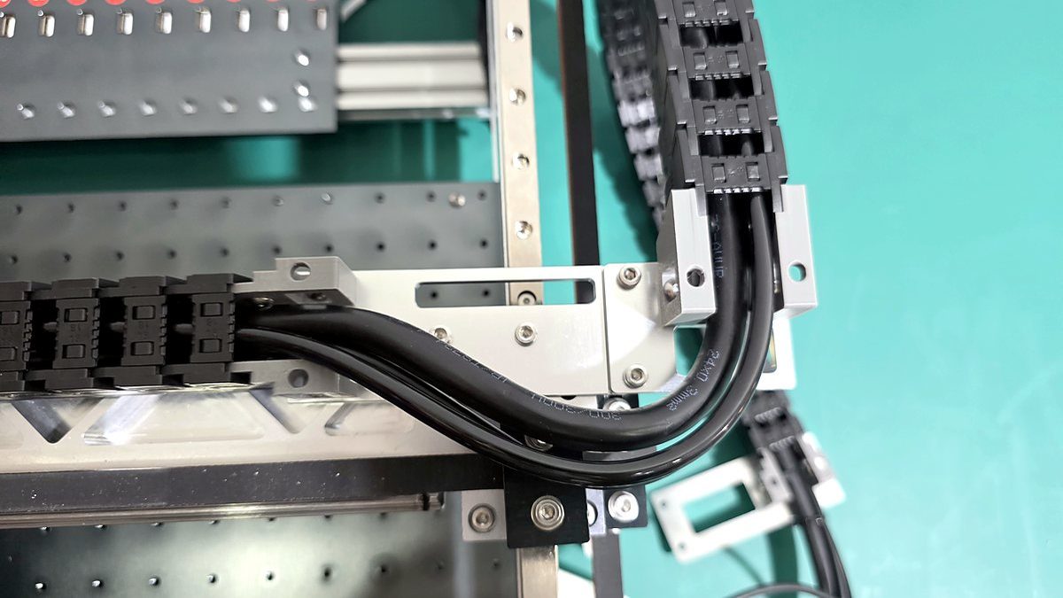
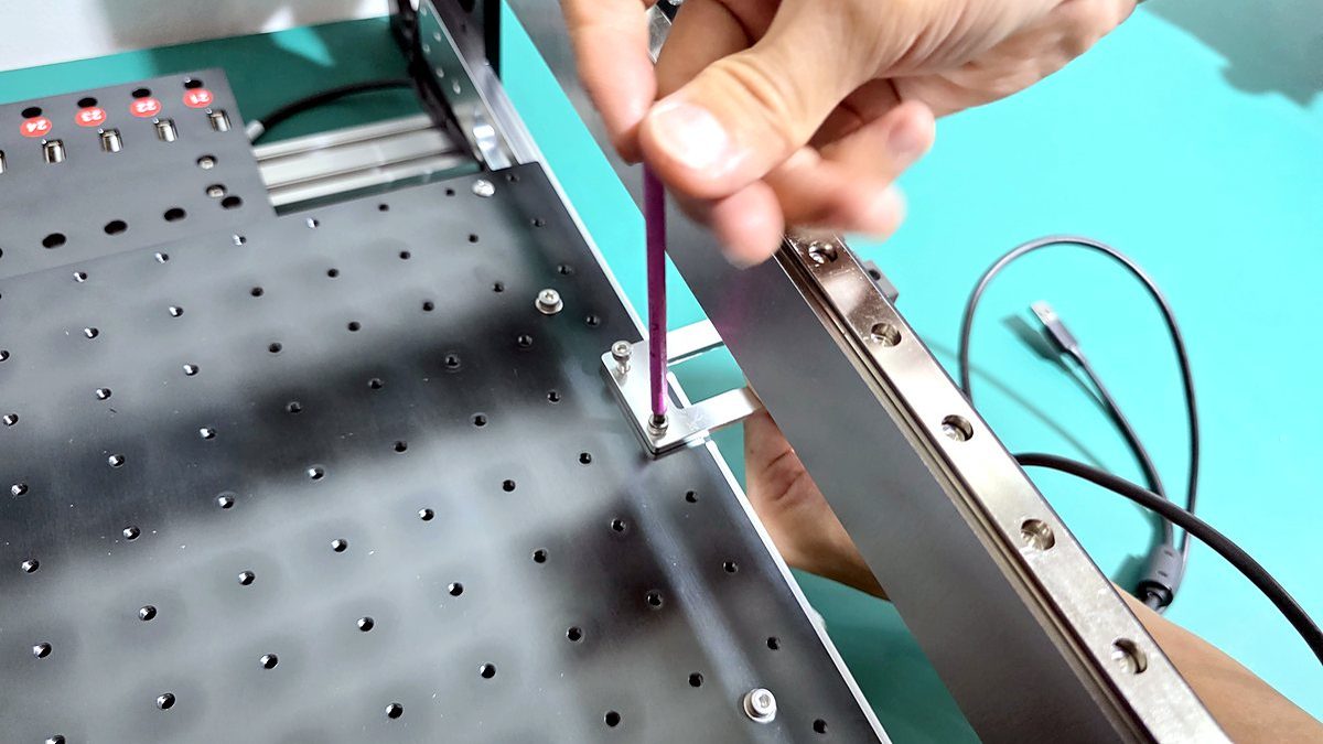
Step 7: Install the Cable Chains
The cable chain set has two sections. The long section moves with the X axis. The short section moves with the Y axis.
Parts and fasteners for this step
- Cable chain set (long and short)
- 8 × M4×10 mm screws (in total)
1. Attach the cable chain to the Z-axis assembly.
2. Attach the cable chain to the X axis.
3. Attach the cable chain to the Y axis.
4. Attach the cable chain to the machine frame.
5. Check the result.

Checkpoint: The X and Y axes move smoothly through full travel and trip their limit switches. The Z-axis assembly is mounted. The cable chains are attached at the Z-axis assembly, X axis, Y axis, and frame.
Part 4: Fixtures
Install the PCB clamp and the nozzle station.
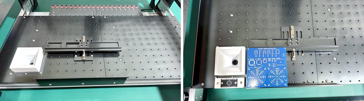
Step 8: Install the PCB Clamp
The PCB clamp has two parts: a fixed part and a movable part.
Parts and fasteners for this step
- PCB clamp set (fixed part and movable part)
- 3 × M4×8 mm screws and 3 nuts (fixed part)
- AFARCO demo PCB (optional, for the check in this step)
1. Assemble the fixed part with three M4×8 mm screws and three nuts.
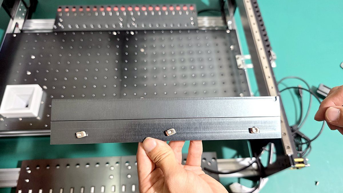
2. Place the fixed part on the machine frame.
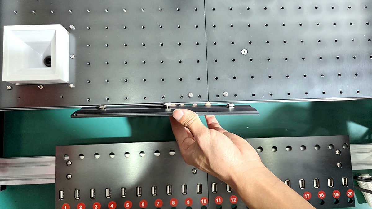
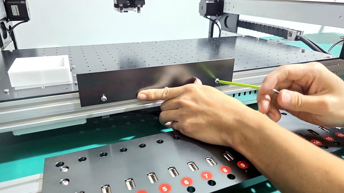
3. Tighten the screws.
4. Install the movable part on the tabletop. Adjust its position to fit your PCB size.
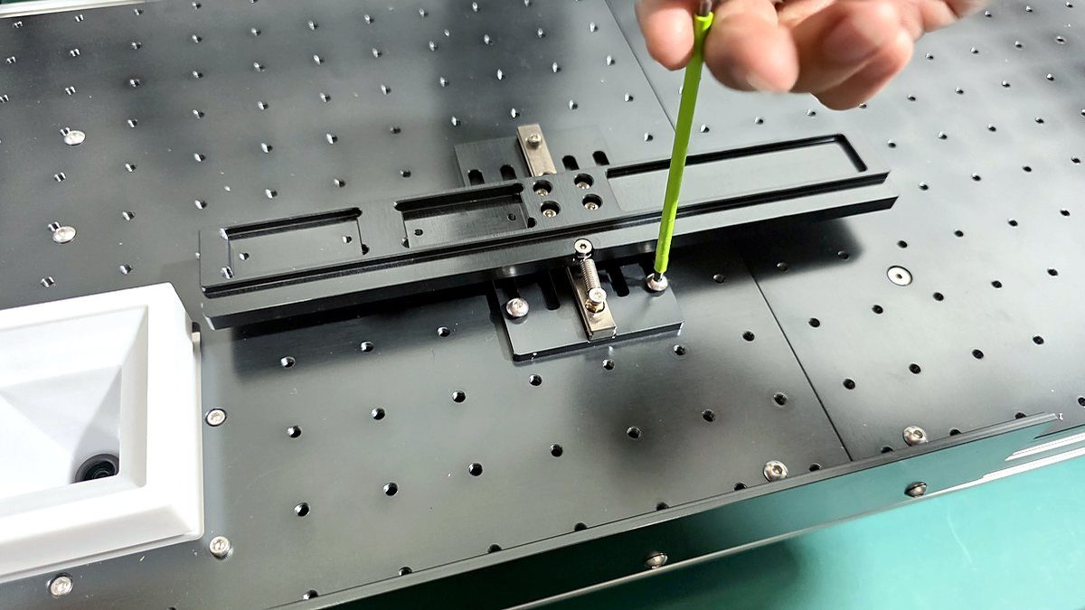
5. Check the result.
Step 9: Install the Nozzle Station
The 6-position nozzle station holds the nozzles during automatic nozzle changes.
Note: The six magnets are not included in the kit because of shipping restrictions on magnetic items. Obtain six disc magnets locally: 10 mm diameter, 2 mm thick, with a 3 mm center hole.
Parts and fasteners for this step
- 6-position nozzle station
- 6 disc magnets, Ø10 × 2 mm, Ø3 mm hole (not included)
- 4 × M4×8 mm screws
1. Install the six magnets in the six drilled positions marked in red. The magnets hold the nozzles in place.
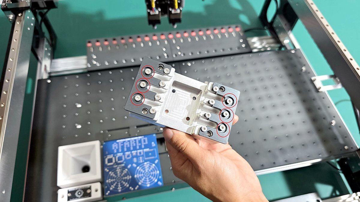
2. Mount the nozzle station on the tabletop with four M4×8 mm screws.
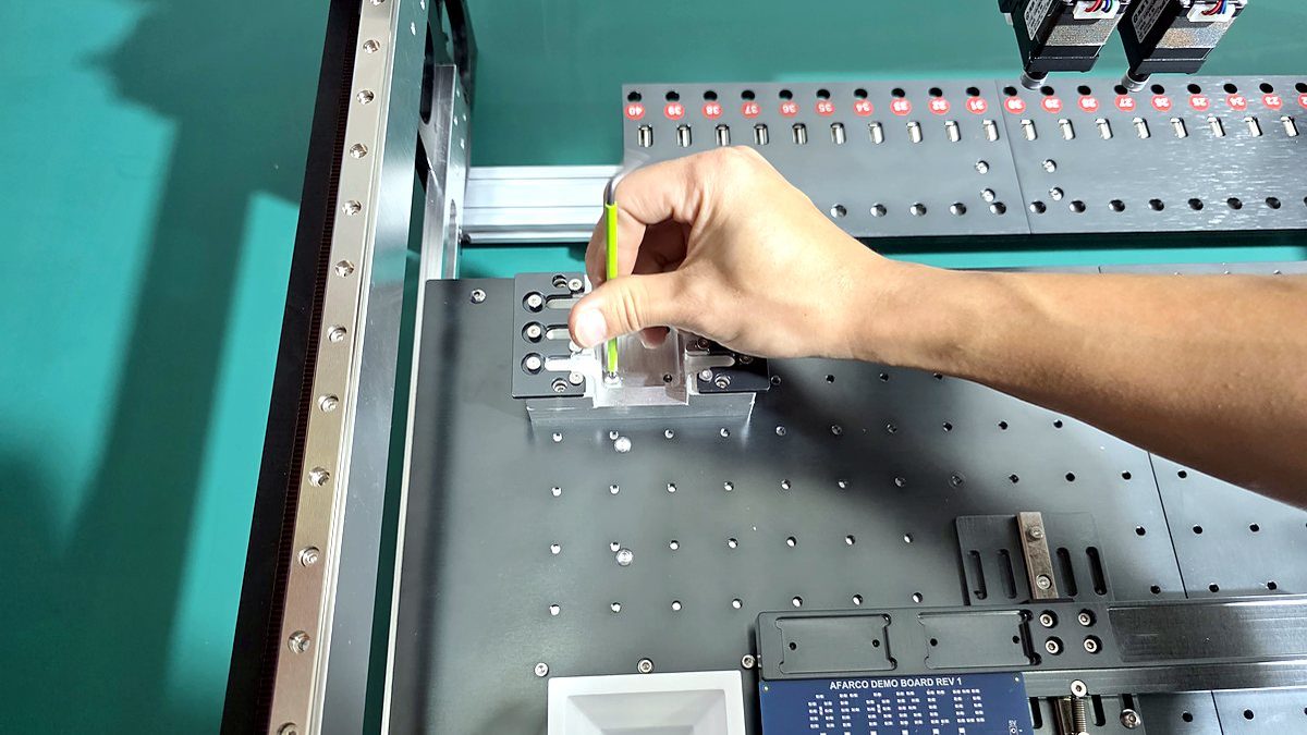
Note: The nozzle-change positions are not preconfigured in the software, so you can mount the station anywhere on the worktable. We usually mount it in the left corner to save space.
Checkpoint: The PCB clamp is installed and adjusted to your PCB. The nozzle station is mounted with its six magnets in place.
Part 5: Electronics and Power
Connect all cables, power up, and connect the computer.
Step 10: Connect the Cables and Power
Make all cable connections first. Connect AC power last.
A. Z-axis assembly
1. Connect the X-Motor cable (4-pin) and the X-Limit cable (3-pin) to the Z-axis assembly.
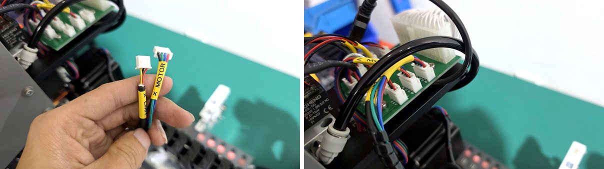
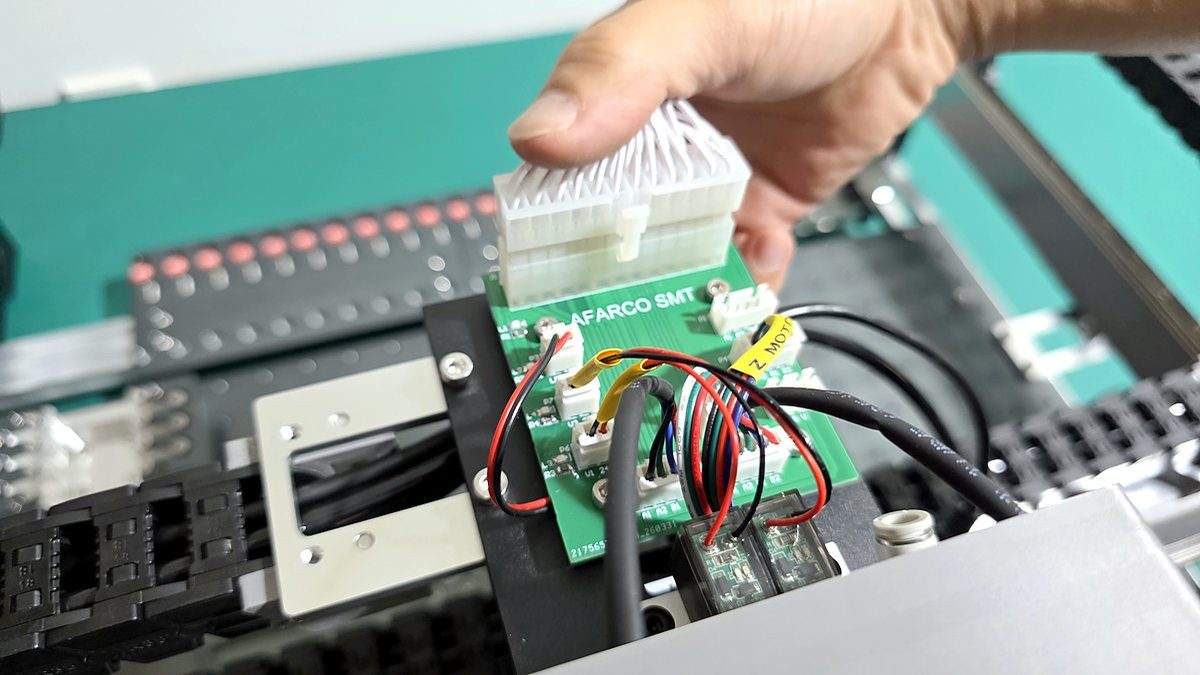
2. Connect the 24-pin cable to the Z-axis assembly.
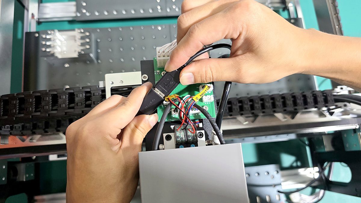
3. Connect the USB camera cable to the Z-axis assembly.
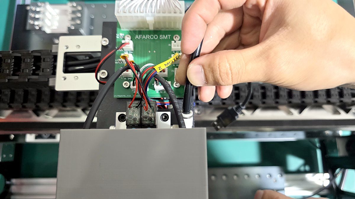
4. Connect the vacuum hose to the Z-axis assembly.
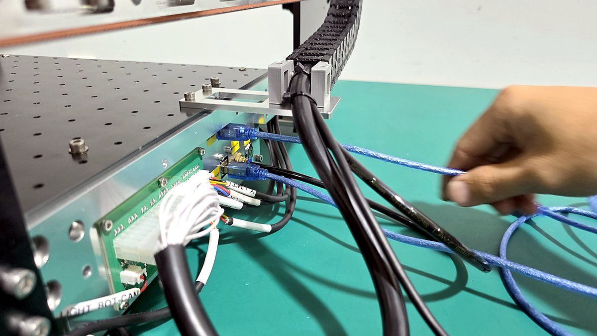
B. Control box
1. Connect the Y2-Motor cable to the Y2-Motor header.
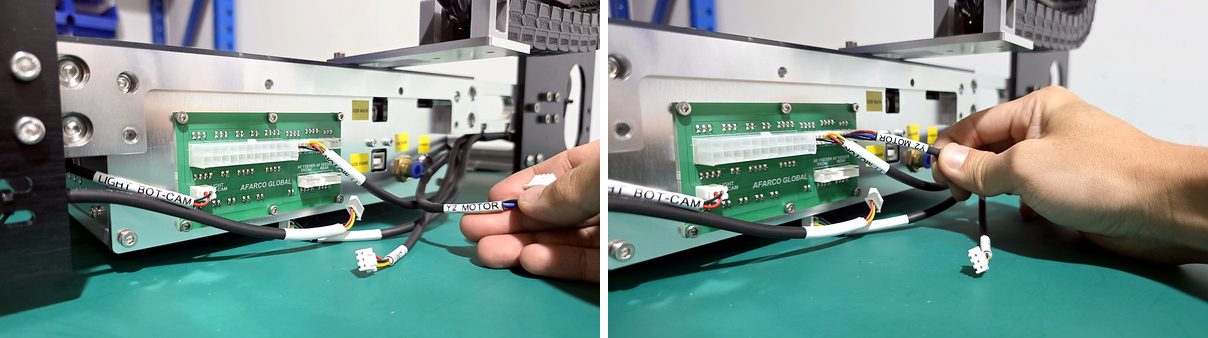
2. Connect the Y-Limit cable to the Y-Limit header.
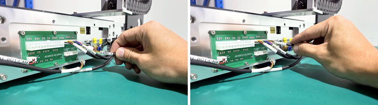
3. Connect the Feeder-Front and Feeder-Rear cables to the AF Feeder Front and AF Feeder Rear headers.
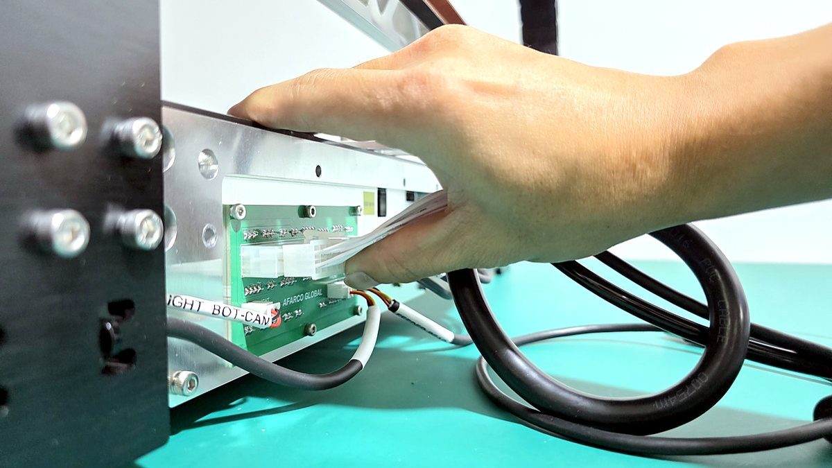
4. Connect the 24-pin cable to the control box.
5. Connect the other end of the vacuum hose to the control box.
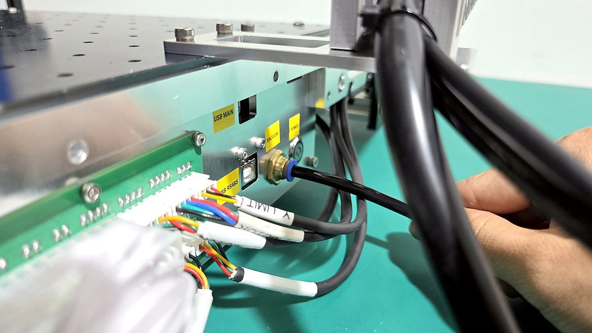
6. Connect the two USB Type-A to Type-B cables to the control box: one to USB MAIN and one to USB RS485.
C. AC power
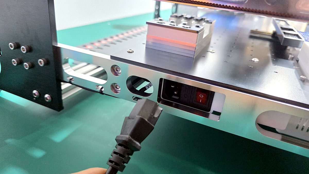
Warning: Confirm that the voltage selector is set correctly (Step 1) before you connect AC power.
1. Connect the IEC power cord to the AC inlet on the left side of the machine.
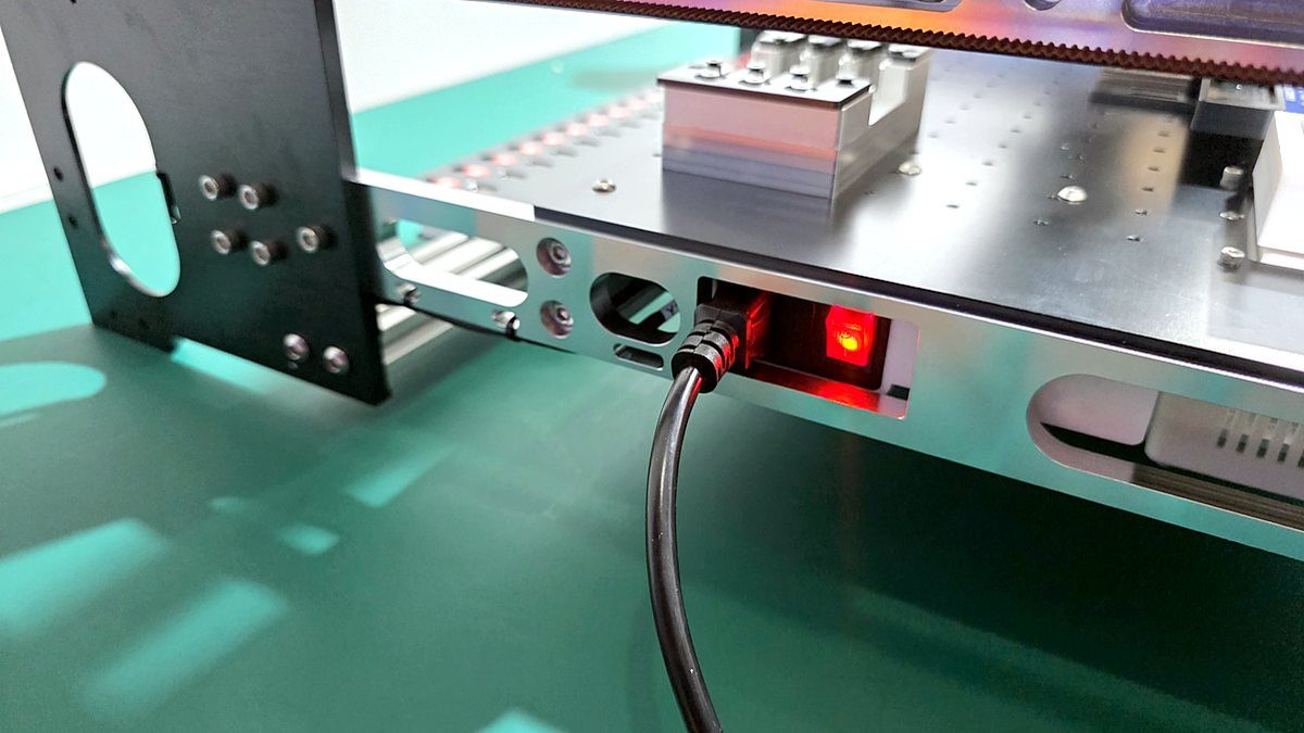
2. Turn on the power switch. The red indicator lights when AC power is present.
D. Computer
1. You now have four USB connectors to connect to the computer: Top Camera, Bottom Camera, USB MAIN, and USB RS485. Connect the two cameras directly to the computer. The USB MAIN and USB RS485 connections can go through a USB hub.
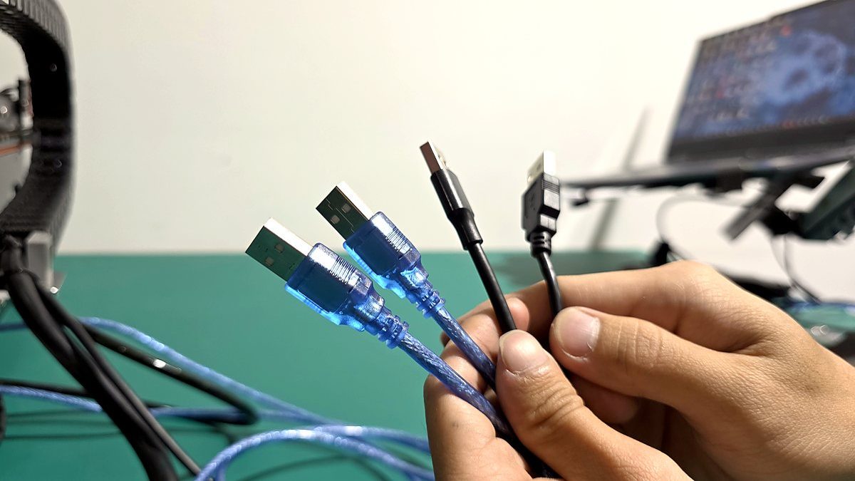
Checkpoint: The red power indicator is on, and the four USB connectors are ready to connect to the computer.
Assembly complete
Before you power on the machine, confirm the following:
- The voltage selector matches your mains supply (Step 1).
- All screws are installed and tight, and the X and Y axes move smoothly through full travel (Steps 2–6).
- The cable chains are attached at the Z-axis assembly, X axis, Y axis, and frame (Step 7).
- All motor, limit, feeder, 24-pin, camera, vacuum, and USB connections are made (Step 10).
- The Top Camera, Bottom Camera, USB MAIN, and USB RS485 connectors are ready to connect to the computer.
shareShare this article